Tuesday, May 26, 2015

Ductless Technology Moves into Ducted ASHPs

Inverters: Efficient, Comfortable, Quiet
Joanna R. Turpin

Once the hallmark of high-efficiency ductless equipment, more manufacturers are incorporating inverter-driven compressors into their ducted air-source heat pump (ASHP) offerings. The reasons for this are simple: Inverter technology improves energy efficiency, provides better comfort, and offers quieter operation.

While consumers have responded positively to these newer energy-efficient products, inverter technology is more expensive and, therefore, mainly offered on higher-end heat pumps (and air conditioners). Even though these systems can cost significantly more than non-inverter ASHPs, manufacturers note their higher price tags are more than offset by significantly higher efficiencies.

Operation and Benefits

My Two Cents: Setting an Adequate Contracting Pricing Policy

The Formula I Use to Appropriately Establish a Sales Price

http://www.achrnews.com/articles/129578-my-two-cents-setting-an-adequate-contracting-pricing-policyhttp://www.achrnews.com/articles/129578-my-two-cents-setting-an-adequate-contracting-pricing-policy

Based on the interest in my Feb. 16 column, “Basic HVAC Contracting Budget Accounting,” I thought it would be worthwhile to follow the financial theme a step further and get into pricing policy. This will not be directed at specific pricing numbers, but the procedures we should each go through when establishing our prices.
One might think that determining selling prices would be a relatively easy task once the costs have been determined. However, I can assure you, based on personal experience and some classes I have presented, even the most intelligent and supposedly sophisticated contractors do not always arrive at the selling price they want and intend to use. While this may seem elementary, I encourage you to stick it away some place and refer to it occasionally to make sure you are not skipping an important step. This system applies to whatever your company overhead may be or whatever net profit you are seeking to achieve.
Remember, your overhead percentage is determined by your ability to perform a certain amount of work. If you are going to do less work, your overhead percentage goes up. Unfortunately, when most contractors see there is less work available, they tend to lower their prices. This is exactly the opposite of what it should be because their costs are actually increasing due to a higher overhead percentage.

Step No. 1

Monday, May 18, 2015

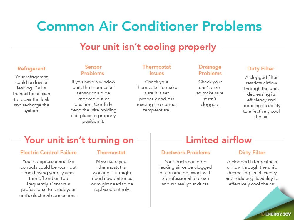
What you need to know to stop your air conditioner or heat pump from losing its cool.

http://www.carrier.com/homecomfort/en/us/for-owners/#0

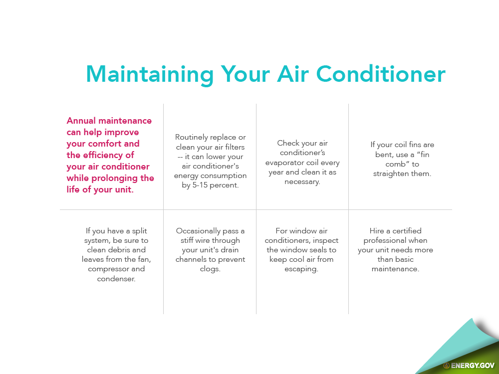
No matter how energy-efficient your air conditioner was when it was installed, it can lose efficiency if not properly maintained. The good news is, it isn’t hard, time-consuming or expensive to do the kind of upkeep that can he
lp your unit last for years:
  • Change your air filters regularly. A clogged or improperly installed air filter makes your system work harder. So, if you forget to change your filters, you might notice you’re paying more for air conditioning that you’re not enjoying nearly as much.
  • Be sure not to block your floor, wall or ceiling vents. When drapes, furniture, toys or anything else blocks the vents, it will restrict the airflow—and decrease the system’s efficiency and life span.
  • Check your outside condensing unit periodically to make sure it isn’t covered up or clogged with leaves or debris. Give it space—at least a foot—by cutting back shrubs or tall grass. Air needs to flow in through the sides to cool the coil.
  • Check the drain system to make sure it isn’t clogged. Because your air conditioner removes humidity from your home during the cooling season, you should notice water trickling from the condensate drain of the indoor unit. Keep in mind that the drainage will be limited if you live in a very dry environment.
  • Don’t try to turn your home into an icebox. You shouldn’t run your system in cooling mode when outdoor temperatures are lower than 55°F/12.78°C unless your outdoor unit is modified to handle cooling in colder weather.
  • Have a Carrier® expert clean your indoor coil and replace your filters routinely. If you notice longer operating cycles and reduced energy efficiency, the coil could be to blame.
  • Check for water in the base of your outdoor unit. It likely means the support base has settled or shifted since installation and is no longer level. If that’s the case, be sure to re-level it to assure proper drainage. Also check for standing water or ice under the unit in and arrange for it to drain away.
  • Consider having your ducts sealed or insulated. Air leaks can lead to wasted energy and an overworked air conditioner.
Think of it this way: By investing a little time and money in keeping your unit operating at peak performance, you stand to save a lot in system repair and energy bills. Of course, if you’re not up to the task, your local Carrier®expert can take care of all the above, and much more.

Wednesday, May 6, 2015

Tech Tip of the Month with Phil Hrenak

Hi-Velocity Duct rules of thumb


  • 8” duct required for 1.5- 3 ton systems
  • 10” duct required for 3.5 & five ton systems
  • 14” insulated return duct for 1.5-3 ton systems, 16” for 3.5 ton, 4 ton & 5 ton systems
  • Minimum eight 2” outlets per ton Minimum four “super duct” outlets per ton 
  • Minimum 10’ length on a run (even if you have to coil up the run)
  • Systems operate at 250 CFM per ton, 30 CFM per 2” outlet, 60 CFM per super duct outlet 
  • Outlet packages come in 10’ = 100% Air Flow and 15’ = 90% Air Flow
  • (Adding a 5Ft splice or 20’ = 80% Air Flow)
  • (Adding a 10Ft Splice or 25’= 65% Air Flow)
  • HEZ blower unit can be ordered as 230 or 115 volt units
  • Chilled Water Coil Delta T = 8 to 10 DegF@ 44 EWT & 2.5 GPM per Ton
  • Delta T Air side 15-20 Deg F, Delta T across coil for better humidity removal should be 29 DegF Must have a minimum of 18” of strait duct directly off the unit prior to elbow or tee. 
  • Use branch take-offs rather than bull head tees. 
  • Bullhead tees must have maximum 60/40 balance. 
  • Branch take-offs allow for up to 70/30. 


CFM per outlet= FPM x .022 for 2” FPM x .042 for HE

Monday, April 27, 2015

Customer Awareness, Internet of Things Influence IAQ Products

IAQ Products Becoming Smarter, More Connected than Ever Before

CHICAGO — As consumers become increasingly aware of the quality of the air inside their homes and workplaces, installers and manufacturers are working to meet consumers’ growing demands for products that measure, humidify, dehumidify, filter, clean, and sanitize the air. At this year’s AHR Expo in Chicago, manufacturers displayed and demonstrated some of the many new products they have developed to help both the contractor and the end user achieve the best possible IAQ.

A Growing Awareness

The biggest thing driving innovation is the customer, said J. Paige Freeland, marketing, General Filters Inc. “People are

Monday, April 6, 2015

How to Check and Charge a R-410A Refrigeration System


Tech Tip of the Month with Phil Hrenak

1.Inspect the coils, blower wheels and the blower motor speed to insure they are operating properly. Using the temperature rise method (CFM = KW(Volts X Amps) X 3.413 divided by (Temp rise X 1.08)), check the airflow. Using the manufacturer’s coil specification sheets, confirm the pressure drop across coils. The airflow measurement is used to find the evaporator load, so it must be accurate 

2. Check the system operating pressures. Attach the hoses from the manifold gauge to the pressure taps on the liquid and suction service valves. Service valve locations can be found anywhere within the outside cabinet, but generally they are located near the coil. Read and record the information on the pressure gauges for liquid and suction with the pencil and paper. 

3. Using the outdoor thermometer, measure and record the outdoor temperature. 

4. Measure the dry bulb temperature by placing a thermometer where air goes to the indoor unit in the return duct. Wrap the thermometer bulb in wet cloth and then measure the wet bulb temperature the same way as the dry bulb measurement, recording the results. This is an important step since it finds the evaporator load that’s having a key effect on system pressures. 

5. Measure the liquid-line temperature to determine sub-cooling. Use a liquid-line thermometer that has a probe that can be tightly attached to the line. Place the attachment approximately 6 inches from the liquid service valve. Write down the measurement results. 

6. Connect the hoses from your manifold gauge to the pressure taps on the liquid and suction service valves. Measure and record the liquid and suction pressures. Measure the high side pressure at the service valve pressure tap for the liquid-line. Use a pressure conversion chart to change the high side pressure to saturated temperature. Deduct the liquid-line temperature from the saturation temperature of R-410A refrigerant in the condenser to compute the sub-cooling value. On the manufacturer’s data sheet find the correct operating pressures for the circumstances found for the measured air. Also look at the sheet for needed sub-cooling levels. 

7. Charge the unit with enough R-410A to meet the manufacturer’s specification if, based on the information from their data sheet, there may be a too low sub-cooling problem. If this is the case, it is most likely due to lack of refrigerant. Sub-cooling temperatures that are too high may be due to an excess of refrigerant in the condenser, but it may also be a failed TVX (Thermostatic Expansion Valve) or line restriction. It’s important to check both high and low side pressures to determine if any of these issues are present. 

If there is no line restriction and the TVX is working correctly, siphon off enough R-410A refrigerant until the pressure reading is at the level suggested by the manufacturer. Use a refrigerant recovery machine to safely transport the coolant as it is illegal to release R-410A into the air.